Synchronizing large-scale facilities such as free-electron lasers or telescopes requires an intelligent solution to bring the timing signal to remote locations. This is the purpose of Cycle’s PULSE Timing Distribution System (TDS). PULSE offers few-femtosecond precision timing distribution over kilometer-long distances. By translating the timing signal to the optical domain, it ensures higher robustness against environmental influences and better options to correct fluctuation compared to commonly used TDS in the electromagnetic domain. How can Cycle’s TDS ensure such high accuracy?
The general idea of an optical TDS is to use an optical timing signal provided by an optical master oscillator (OMO) and distribute this signal via a fiber-optic link network to the remote stations of your facility. An ultra-low noise mode-locked laser generates the timing signals in optical pulse trains as OMO to achieve maximum timing stability.
This highly stable timing signal is transmitted via polarization-maintaining optical fibers to the remote clients. Nevertheless, even the most stable mode-lock laser cannot correct for environmental fluctuations occurring during the transmission.
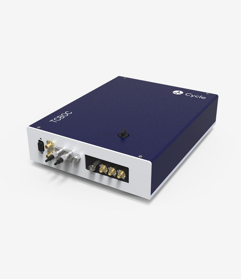
Hence, the fiber links are additionally timing-stabilized by a sophisticated feedback system that measures and corrects for fluctuations of the timing signals that occur upon transmission. The feedback system partially reflects the timing signal at the remote stations and can compare the incoming and outgoing laser pulses utilizing Balanced Optical Cross-correlators (BOC). This way, environmental changes of the fiber are detected, and by using an optical delay line, the timing signal is adjusted accordingly.
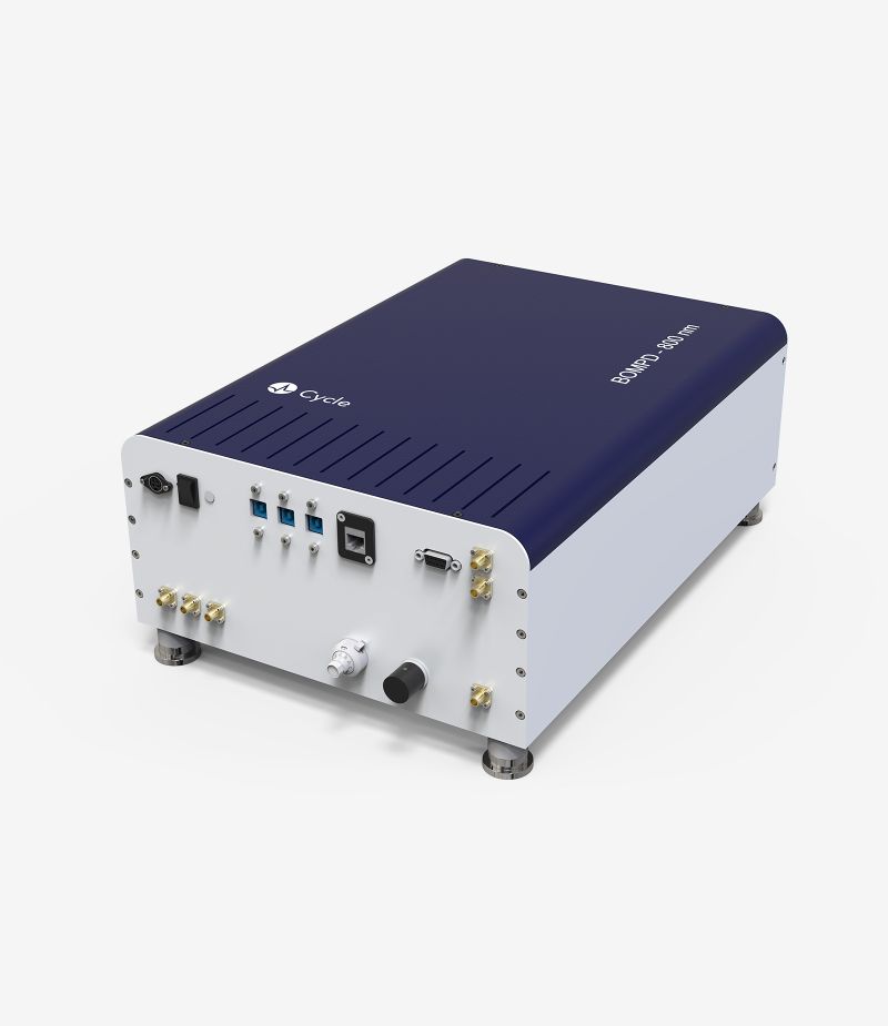
Though the exact interplay of those and other high-precision elements like the BOMPD, Cycle’s PULSE TDS provides a substantially drift- and jitter-free timing distribution and makes an essential contribution to cutting-edge research.

Figure 1 – Layout of the timing distribution system (top sketch) and its individual modules as built in the lab (bottom pictures). RMO: RF master oscillator; OMO: optical master oscillator; TSP: temperature-stabilized platform; FLS: fiber link stabilizer; TCBOC: two-color balanced optical cross-correlator; BOMPD: balanced optical-microwave phase detector. Şafak et al. (2017)


