1. Introduction
In the early 2000, the group of Franz Kärtner at the Massachusetts Institute of Technology (MIT) was facing a difficult task: they were working on the MIT X-ray laser project with the goal of constructing a national user facility based on an intense free-electron laser (FEL). But the existing methods for synchronizing large accelerators could not provide the timing accuracy necessary for the new laser facilities comprising an X-ray FEL. So, they had to come up with a new idea.
2. Challenge
In general, to synchronize a train of light pulses with an electrical oscillation one needs to convert the two signals into the same form. Until 2004, this happened mostly by converting the photons of the light pulses into electrons using “direct photodetection”. From the photodetector’s readout, a sinusoidal wave is generated and compared to the microwave signal, where the phase error can be detected.
The direct photodetection was easy to implement and therefore it is widely used despite the additional phase noise from amplitude fluctuations during detection. However, its timing resolution is limited to around 100 fs using traditional microwave mixers. Therefore, the advanced accelerator facilities and especially free-electron lasers needed a much better timing accuracy.
In order to overcome the limitations of direct photodetection, Franz Kärtner and his group jointly with Mike Perrott challenged the traditional approach of transferring the light into an electrical signal before comparing the two signals. If it would be possible to translate the information about the timing offset between the microwave signal and the optical signal in the optical domain, this would avoid the above limitations. And the limited timing characteristics of the photodetectors would not restrict the timing performance of the detector. In technical terms, the group’s idea was to translate the phase error between the microwave signal and the optical pulse train into an intensity difference between two optical signals.
3. Solution
In general, to synchronize a train of light pulses with an electrical oscillation one needs to convert the two signals into the same form. Until 2004, this happened mostly by converting the photons of the light pulses into electrons using “direct photodetection”. From the photodetector’s readout, a sinusoidal wave is generated and compared to the microwave signal, where the phase error can be detected.
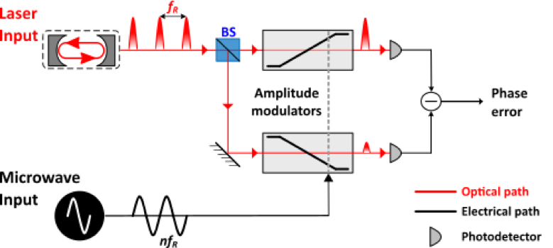
Figure 1 — Schematics of a Balanced Optical Microwave Phase Detector (BOMPD)
As in direct photodetection, the BOMPD receives two input signals: an optical pulse train and a microwave signal. But instead of detecting the optical raw signal and comparing the phase difference between two microwave signals, the BOMPD does two different things: First, it translates the microwave signal into an optical amplitude modulation. And second, it detects the modulated signal using a balanced detector.
As shown in Figure 1, the BOMPD splits the incoming laser into two equal paths and sends them to two electro-optic amplitude modulators to alter the amplitude of these laser pulses according to the microwave signal. The input pulses can be modified between zero transmission and full transmission. And after the modulation, the two paths are then detected using a balanced photodetector creating the difference signal between the two paths intensities.
If one of the modulated pulses is completely suppressed in the modulator, the other one is fully transmitted by the other modulator. In this case, the balanced detection shows its maximum value. And if both input pulses arrive at the zero-crossings of the microwave, the modulation leaves the pulse transmit unchanged, the signal at the balanced detection leads to zero voltage as both arms cancel each other. This also shows the big advantage of a balanced detection: It cancels any intensity fluctuations of the laser input signal.
When monitoring the output signal of the balanced photodetector over time, it reveals the phase correlation between the laser input signal and the microwave input signal. If the signals are in perfect sync, a constant voltage will be the result at the output. For a constant phase shift between the microwave and the laser pulses, this voltage level will shift. And if the microwave and the laser run at different frequencies, the output signal will show a changing voltage signal that oscillates with the frequency difference of both signals, the so called “beat frequency”. Although it is in principle enough to modulate only one arm of the BOMPD, modulating both arms increases the sensitivity of phase detection and adds the possibility of a zero-crossing in the phase-voltage curve at the output which is preferable when using the phase error for locking applications.
When Franz Kärtner and his group started to implement the BOMPD setup, they took advantage of a unique property of the coherent laser light – interference. Interferometers offer a straightforward way to modulate the amplitude of an optical signal and directly provide a modulation of both arms of the interferometer with the necessary phase difference of 180° between the signals.
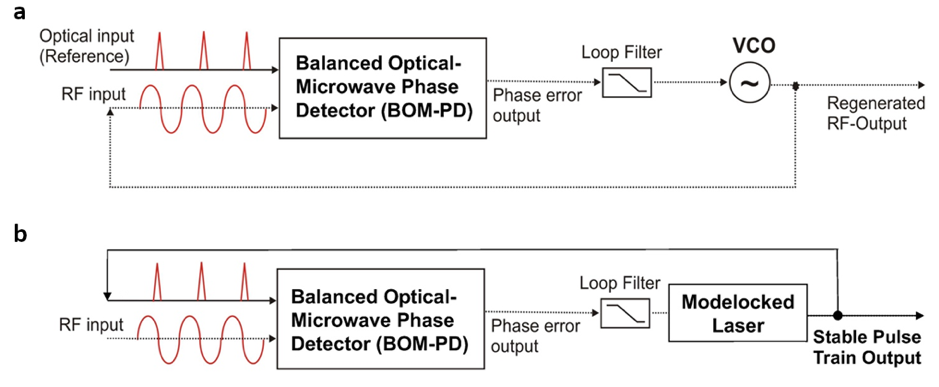
Kärtner’s system used a combination of phase modulator and a Sagnac loop. This allowed to further reduce the influences of environmental fluctuations like temperature or vibrations. With their BOMPD, they could successfully synchronize a low noise VCO to a femtosecond fiber laser, or vice versa, (see Fig. 2a and 2b, respectively).
4. BOMPD Technology Today
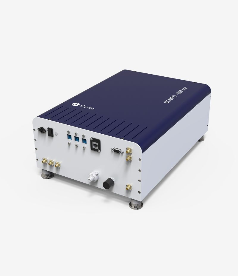
Current standard versions of the BOMPD now offer a timing jitter below 20 fs. Lower timing jitter is available on request and in special cases even sub-fs performance can be achieved. The systems stay in lock for the long term with a timing drift of less than 20 fs rms over 10h. And because of its low noise floor, measurements with the BOMPD offer a timing resolution of < 0.5 fs.
The BOMPD’s sensitivity is determined by the linear slope around the zero-crossing in units V/fs. With typical values beyond 0.1 mV/fs, its sensitivity is up to two to three orders of magnitude higher than standard direct photodetection, which makes the BOMPD well-suited for high precision timing measurements and synchronization tasks.
Franz Kärtner says: “Without a BOMPD and its underlying principles, synchronization between microwave subsystems and optical lasers would be impossible to achieve in modern Free Electron Laser facilities.”
5. Applications
For more than a decade, the BOMPD technology has been in operation in large accelerator facilities around the world, like FERMI in Trieste or at the Dalian Coherent Light source and Shanghai XFEL in China. In these facilities, the BOMPD helps wherever high accuracy between optics and electronics is necessary.
Facilities
-
Dalian Coherent Light source
-
Shanghai XFEL in China
Applications
It helps bringing the facilities’ lasers and microwave sources in sync and keeping them locked on the long-term. Or it helps (re-)generating RF-signals from a stable master laser oscillator. Research labs are increasingly using the BOMPD as a precise device for timing jitter measurements.
“Large accelerators are far from the only field of application.” continues Prof. Kärtner. “The BOMPD can help in any application where femtosecond-timing is needed.” Cycle GmbH, a Hamburg-based company founded by Kärtner, continues to improve the performance of the BOMPD. Cycle also broadens the application spectrum into other fields such as time-resolved electron diffraction or microscopy or precise microwave generation. And with this ongoing work, more and more researchers will benefit from the BOMPD’s precise electro-optic synchronization.
